Electrical Wire Calculator
Fast AWG & load calculator • 2026 codes
Electrical Wire Formula:
Show the calculator\( V_d = \frac{2 \times L \times I \times R}{1000} \)
Where:
- \( V_d \) = voltage drop in volts
- \( L \) = one-way distance in feet
- \( I \) = current in amperes
- \( R \) = resistance per 1000 feet (Ω/kft)
This formula calculates voltage drop in copper conductors. Maximum recommended voltage drop is 3% for branch circuits and 5% for feeders. Wire gauge selection is based on ampacity, which determines safe current-carrying capacity.
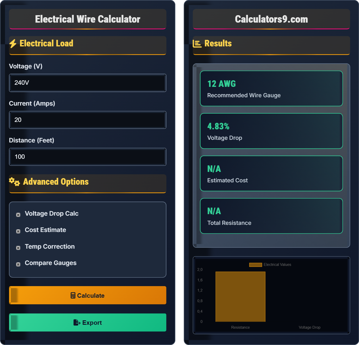
Example: For 100 feet of 12 AWG copper wire carrying 15 amps:
Resistance of 12 AWG = 1.93 Ω/kft
Voltage drop = (2 × 100 × 15 × 1.93) ÷ 1000 = 5.79 volts
Percent drop = (5.79 ÷ 120) × 100 = 4.83%
This exceeds the 3% recommendation, suggesting 10 AWG wire.
Electrical Load
Advanced Options
Results
| Parameter | Value |
|---|
| Specification | Value |
|---|
Comprehensive Electrical Guide
Electrical wire is classified by American Wire Gauge (AWG), which defines the cross-sectional area and current-carrying capacity. Smaller AWG numbers represent larger wire diameters. Copper is the standard conductor material for most applications. Wire ampacity depends on insulation type, ambient temperature, and installation method. Proper wire sizing prevents overheating, voltage drop, and potential fire hazards.
The voltage drop calculation uses the following formula:
Where:
- \(V_d\) = Voltage drop in volts
- \(L\) = One-way distance in feet
- \(I\) = Current in amperes
- \(R\) = Resistance per 1000 feet (Ω/kft)
Maximum recommended voltage drop is 3% for branch circuits and 5% for feeders.
Electrical installations must comply with National Electrical Code (NEC) requirements:
- Ampacity: Wire must handle circuit current without exceeding temperature rating
- Voltage Drop: Maximum 3% for branch circuits, 5% for feeders
- Derating: Adjustments for temperature and conduit fill
- Protection: Proper breaker/fuse sizing for wire gauge
- Grounding: Equipment grounding conductor requirements
- Conservative sizing: Use larger wire when in doubt
- Future expansion: Plan for increased loads
- Temperature considerations: Derate in high-temperature environments
- Conduit fill: Account for derating with multiple conductors
- Professional consultation: Complex installations require licensed electrician
Electrical Fundamentals
American Wire Gauge system defining wire diameter and current capacity.
\(V_d = \frac{2 \times L \times I \times R}{1000}\)
Where Vd=voltage drop, L=distance, I=current, R=resistance per kft.
- Smaller AWG numbers = larger wire diameter
- Max voltage drop: 3% for branch circuits
- Proper breaker sizing for wire gauge
Installation Guidelines
14 AWG: 15A, 12 AWG: 20A, 10 AWG: 30A, 8 AWG: 40-50A, 6 AWG: 55-65A
- Branch circuits: 3% maximum
- Feeders: 5% maximum
- Overall: 5% maximum
- Wire resistance increases with length
- Higher temperatures reduce ampacity
- Multiple conductors require derating
Electrical Wire Calculation Learning Quiz
Which of the following statements about American Wire Gauge (AWG) is CORRECT?
The answer is C) 12 AWG is thicker than 14 AWG. In the American Wire Gauge system, smaller numbers represent larger wire diameters. Therefore, 12 AWG wire is physically thicker than 14 AWG wire. This is counterintuitive to many people who expect larger numbers to mean larger size. The system is logarithmic, with each gauge number representing a specific cross-sectional area.
Understanding the inverse relationship between AWG numbers and wire diameter is fundamental in electrical work. This counterintuitive system means that as the AWG number decreases, the wire gets thicker and can carry more current. Students often confuse this relationship, thinking larger numbers mean larger wires. Remember: 1 AWG is the largest common size, while 40 AWG is very thin wire.
AWG: American Wire Gauge - standardized wire diameter measurement
Ampacity: Maximum current a conductor can safely carry
Conductor: Material that allows electricity to flow
• Smaller AWG numbers = larger wire diameter
• Larger diameter = higher current capacity
• 12 AWG > 14 AWG in thickness and capacity
• Think "lower number, larger wire"
• 12 AWG can handle more current than 14 AWG
• Remember: 1 AWG is very thick, 40 AWG is very thin
• Confusing larger AWG numbers with larger wire diameter
• Using smaller wire than required for circuit amperage
• Not understanding the inverse relationship
Calculate the voltage drop for 100 feet of 12 AWG copper wire carrying 15 amps at 120V. The resistance of 12 AWG is 1.93 ohms per 1000 feet.
Step 1: Apply voltage drop formula: \(V_d = \frac{2 \times L \times I \times R}{1000}\)
Step 2: Substitute values: \(V_d = \frac{2 \times 100 \times 15 \times 1.93}{1000}\)
Step 3: Calculate: \(V_d = \frac{5790}{1000} = 5.79\) volts
Step 4: Calculate percentage: \(\frac{5.79}{120} \times 100 = 4.83\%\)
Therefore, the voltage drop is 5.79 volts (4.83%).
This problem demonstrates the voltage drop calculation, which is critical for proper wire sizing. The factor of 2 accounts for the round trip (out and back). The 1000 in the denominator converts from per-kilofeet to per-foot basis. Since 4.83% exceeds the recommended 3% for branch circuits, a larger wire gauge would be needed.
Voltage Drop: Reduction in voltage along a conductor
Resistance: Opposition to current flow, measured in ohms
Round Trip: Current path to load and back
• Factor of 2 accounts for round trip
• Max voltage drop: 3% for branch circuits
• Use larger wire if drop exceeds limits
• Remember the factor of 2 for round trip
• 120V circuits: max 3.6V drop (3%)
• 240V circuits: max 7.2V drop (3%)
• Forgetting the factor of 2 for round trip
• Not converting resistance properly
• Not checking against voltage drop limits
An electrician needs to install a 20-amp circuit using copper wire. According to NEC requirements, what is the minimum acceptable wire gauge, and why is proper breaker sizing critical?
For a 20-amp circuit, the minimum acceptable wire gauge is 12 AWG copper. According to NEC Table 310.15(B)(16), 12 AWG THWN copper wire has an ampacity of 25 amps at 60°C, which is sufficient for a 20-amp circuit. Proper breaker sizing is critical because the breaker protects the wire from overheating. If a 30-amp breaker were used with 12 AWG wire, the wire could overheat and cause a fire before the breaker trips.
This example demonstrates the critical relationship between wire gauge and circuit protection. The breaker is sized to protect the wire, not just the connected load. The wire must be able to safely carry the current that the breaker will allow to flow. This is a fundamental safety principle in electrical work.
Ampacity: Maximum current a conductor can safely carry
Circuit Protection: Device that prevents overcurrent
NEC: National Electrical Code standards
• Breaker protects wire, not just load
• Wire must handle breaker-rated current
• Follow NEC ampacity tables
• 14 AWG = 15A circuit max
• 12 AWG = 20A circuit max
• 10 AWG = 30A circuit max
• Oversized breaker for wire gauge
• Undersized wire for circuit amperage
• Not following NEC requirements
A wire run will be exposed to 104°F ambient temperature. How does this affect the ampacity of 12 AWG copper wire rated for 90°C insulation, and what adjustment factor should be applied according to NEC Table 310.15(B)(2)(a)?
According to NEC Table 310.15(B)(2)(a), at 104°F (40°C) ambient temperature, the correction factor for 90°C rated conductors is 0.91. If the base ampacity of 12 AWG copper wire is 30 amps at 30°C (86°F), the adjusted ampacity would be: 30 × 0.91 = 27.3 amps. This means the wire can now safely carry only 27.3 amps instead of 30 amps due to the higher ambient temperature.
This demonstrates how ambient temperature affects wire capacity. Higher temperatures reduce the wire's ability to dissipate heat, therefore reducing its safe current-carrying capacity. Electricians must account for environmental conditions when sizing wire. This is especially important in attics, outdoor installations, or areas with heat sources.
Correction Factor: Multiplier for temperature adjustments
Ambient Temperature: Surrounding air temperature
Insulation Rating: Maximum operating temperature
• Higher temperature = lower ampacity
• Apply correction factors from NEC tables
• Consider worst-case temperature conditions
• Use 90°C columns when allowed
• Check ambient temperature corrections
• Consider seasonal temperature variations
• Not accounting for high ambient temperatures
• Using wrong correction factors
• Installing wire in unsuitable locations
According to NEC Article 310.15(B)(3)(a), what happens to wire ampacity when multiple current-carrying conductors are installed in the same conduit?
The answer is C) Ampacity decreases due to heat buildup. When multiple current-carrying conductors are bundled together in a conduit, they generate heat that cannot dissipate as effectively as when installed separately. This heat buildup reduces the safe current-carrying capacity of each conductor. According to NEC Table 310.15(B)(3)(a), derating factors apply: 80% for 4-6 conductors, 70% for 7-9 conductors, and 50% for 10-20 conductors.
Understanding conduit fill is crucial for safe electrical installations. When conductors are bundled together, they create a cumulative heating effect that reduces their individual current-carrying capacity. This is why electrical codes require derating when multiple conductors share the same raceway. Students should remember that the physical constraints of conduits affect electrical performance.
Conduit Fill: Number of conductors in a raceway
Derating: Reducing ampacity for multiple conductors
Raceway: Conduit or cable tray system
• More conductors = lower ampacity per wire
• Apply derating factors from NEC tables
• Grounding conductors typically not counted
• 1-3 conductors: no derating needed
• 4-6 conductors: 80% of normal ampacity
• 7-9 conductors: 70% of normal ampacity
• Not applying derating for multiple conductors
• Counting grounding conductors in derating
• Overfilling conduits beyond NEC limits
FAQ
Q: How do I determine the proper wire gauge for a circuit?
A: Proper wire gauge selection involves multiple factors:
First, determine the circuit amperage from the load requirements. Then consult NEC Table 310.15(B)(16) for allowable ampacities. For example, a 20-amp circuit requires at least 12 AWG copper wire.
Next, calculate voltage drop using the formula: \(V_d = \frac{2 \times L \times I \times R}{1000}\)
For a 20-amp circuit at 120V over 100 feet with 12 AWG wire (R=1.93 Ω/kft):
\(V_d = \frac{2 \times 100 \times 20 \times 1.93}{1000} = 7.72V\)
Percent drop: \(\frac{7.72}{120} \times 100 = 6.43\%\) (exceeds 3% limit, so use 10 AWG)
Q: What's the difference between 12 AWG and 14 AWG wire?
A: The main differences are in diameter, current capacity, and applications:
- 14 AWG: Thinner wire, 15-amp circuits, general lighting and outlets
- 12 AWG: Thicker wire, 20-amp circuits, kitchen and bathroom outlets
- Resistance: 14 AWG has higher resistance (2.52 Ω/kft) than 12 AWG (1.93 Ω/kft)
- Cost: 12 AWG is typically 20-30% more expensive than 14 AWG
Using 12 AWG in place of 14 AWG is always acceptable and provides safety margin, but never use 14 AWG where 12 AWG is required.