Beam Deflection Calculator
Structural engineering tool • Bending moment & shear force
Euler-Bernoulli Beam Theory Formulas:
Show CalculatorDeflection for simply supported beam with point load:
\( \delta = \frac{P \cdot a^2 \cdot b^2}{3 \cdot E \cdot I \cdot L} \)
Bending moment for distributed load:
\( M = \frac{w \cdot x \cdot (L - x)}{2} \)
Shear force:
\( V = \frac{w \cdot L}{2} - w \cdot x \)
Where: P = applied load, E = modulus of elasticity, I = moment of inertia, L = beam length, w = distributed load
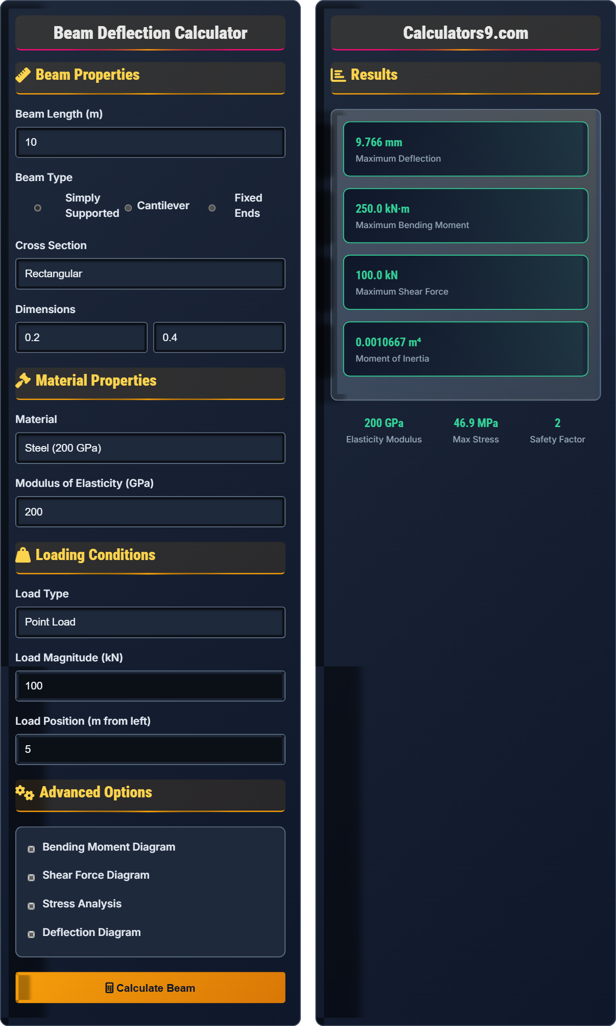
Example: Simply supported beam, 10m long, 100 kN load at center:
\( \delta = \frac{100 \times 5^2 \times 5^2}{3 \times 200000 \times 1000 \times 10} = 0.00208 \) m = 2.08 mm
Beam Properties
Material Properties
Loading Conditions
Advanced Options
Results
Beam Theory Fundamentals
Beam deflection is the displacement of a beam under applied loads. It's governed by the Euler-Bernoulli beam theory, which assumes that plane sections remain plane and perpendicular to the neutral axis during deformation.
Fundamental beam equations:
Where E is modulus of elasticity, I is moment of inertia, and w(x) is distributed load.
- Simply Supported: Pinned and roller supports
- Cantilever: Fixed at one end, free at other
- Fixed-Fixed: Restrained against rotation at both ends
- Continuous: Multiple spans with intermediate supports
Structural Analysis
Bending moment is the internal moment that resists external loads, causing beam curvature. Shear force is the internal force that resists transverse loads, acting parallel to the cross-section.
For rectangular cross-section: \( I = \frac{bh^3}{12} \)
For circular cross-section: \( I = \frac{\pi d^4}{64} \)
Where b = width, h = height, d = diameter.
- Deflection limits (typically L/360 to L/240)
- Stress limits (below yield strength)
- Safety factors (typically 1.5-3.0)
- Serviceability requirements
Beam Deflection Learning Quiz
A simply supported steel beam (E = 200 GPa) is 8 meters long with a rectangular cross-section of 0.2m × 0.4m. A 150 kN point load is applied at 3 meters from the left support. Calculate the maximum deflection and its location. Show all calculations and explain the engineering significance.
Step 1: Calculate moment of inertia
Step 2: Identify parameters
Step 3: Apply deflection formula for point load
Location: Maximum deflection occurs between the load and the center of the beam
Engineering Significance: This deflection is within typical serviceability limits (L/360 = 8000/360 = 22.2 mm).
This calculation demonstrates how beam deflection depends on material properties (E), geometric properties (I), and loading conditions (P). The moment of inertia has a cubic relationship with height, making height the most influential dimension.
The deflection formula shows that longer beams deflect more, stiffer materials deflect less, and larger moments of inertia reduce deflection. This explains why I-beams are efficient - they concentrate material where it's most effective.
Serviceability limits ensure structures remain functional and aesthetically acceptable under normal loads.
Moment of Inertia: Resistance to bending (I = bh³/12 for rectangle)
Modulus of Elasticity: Material stiffness (E = stress/strain)
Neutral Axis: Plane of zero stress in bending
• Deflection is proportional to load magnitude
• Deflection increases with cube of span length
• Moment of inertia is critical for stiffness
• Serviceability limits typically govern design
• Double the height to reduce deflection by 8x
• Halve the span to reduce deflection by 8x
• Use I-beams for efficient material use
• Using wrong units in calculations
• Forgetting to convert dimensions to consistent units
• Using incorrect moment of inertia formula
• Not checking serviceability limits
A cantilever beam of length 4m has a 50 kN point load at the free end and a 10 kN/m distributed load over its entire length. The beam is made of steel with E = 200 GPa and has a rectangular cross-section of 0.15m × 0.3m. Calculate the maximum bending moment, maximum shear force, and maximum deflection. Determine if the beam meets serviceability requirements.
Step 1: Calculate moment of inertia
Step 2: Calculate maximum bending moment
Step 3: Calculate maximum shear force
Step 4: Calculate maximum deflection
Serviceability: L/180 = 4000/180 = 22.2 mm, so 20.5 mm is acceptable.
This problem demonstrates superposition principle - the total effect equals the sum of individual effects. Each load type contributes independently to internal forces and deflections.
For cantilevers, maximum moments and deflections occur at the fixed end, unlike simply supported beams where they typically occur at midspan. The point load dominates the deflection in this case.
Serviceability checks ensure the structure remains functional under normal loads, even if it's structurally adequate for ultimate loads.
Superposition: Principle that effects of multiple loads can be added
Serviceability: Performance under normal service conditions
Cantilever: Beam fixed at one end, free at the other
• Cantilevers have maximum moment at fixed end
• Superposition applies to linear elastic systems
• Serviceability often governs design
• Point loads cause greater deflection than distributed loads
• For cantilevers, deflection ∝ L³
• Distributed loads cause 25% of point load deflection (same total load)
• Check both strength and serviceability
• Forgetting to convert units consistently
• Not applying superposition correctly
• Ignoring serviceability requirements
• Using wrong formulas for beam type
Engineering FAQ
Q: What's the difference between elastic and plastic deflection in beams?
A: The key differences are:
Elastic Deflection:
- Occurs within the material's elastic range
- Deformation is reversible
- Follows Hooke's law (stress ∝ strain)
- Beam returns to original shape when load removed
- Calculated using modulus of elasticity (E)
Plastic Deflection:
- Occurs when stresses exceed yield strength
- Permanent deformation occurs
- Material flows plastically
- Beam retains permanent deformation after unloading
- Design should avoid plastic deflection in service
Structural design focuses on elastic behavior to ensure reversibility and serviceability.
Q: How do I determine the appropriate deflection limit for a beam?
A: Deflection limits depend on several factors:
Building Code Requirements:
- Roof beams: L/180 to L/240
- Floor beams: L/360 to L/480
- Beam with plaster ceilings: L/360
- Beam with no finish: L/180
Functional Requirements:
- Prevent cracking of finishes
- Avoid water ponding on roofs
- Minimize vibration discomfort
- Maintain aesthetic appearance
Occupancy Type:
- Residential: More stringent limits
- Industrial: More relaxed limits
- Equipment-sensitive: Special requirements
Always refer to local building codes for specific requirements.