Capacitor Charge Calculator
Fast RC circuit analysis • 2026 standards
Capacitor Charge Formulas:
Show the calculatorCharging: \( V_C(t) = V_S(1 - e^{-t/RC}) \)
Discharging: \( V_C(t) = V_0 e^{-t/RC} \)
Time Constant: \( \tau = RC \)
Where:
- \( V_C(t) \) = voltage across capacitor at time t
- \( V_S \) = supply voltage
- \( V_0 \) = initial voltage
- \( R \) = resistance (Ω)
- \( C \) = capacitance (F)
- \( t \) = time (s)
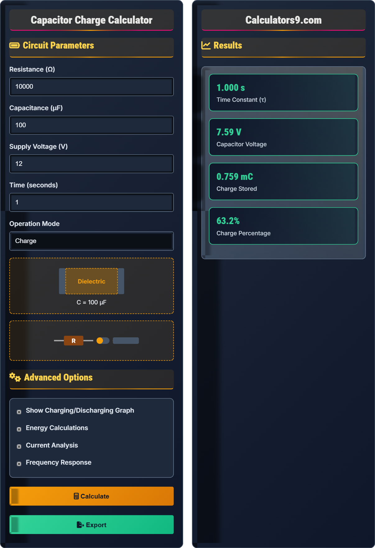
These formulas describe the exponential charging and discharging behavior of capacitors in RC circuits. The time constant τ represents the time to reach 63.2% of final voltage during charging.
Example: For R=10kΩ and C=100μF, τ = 10,000 × 0.0001 = 1 second. After 1 second, the capacitor reaches 63.2% of the supply voltage.
Circuit Parameters
Advanced Options
Results
| Parameter | Value |
|---|
| Time (τ) | % Charged | Voltage (V) |
|---|
Comprehensive Capacitor Guide
A capacitor is a passive two-terminal electrical component that stores energy electrostatically in an electric field. Unlike resistors which dissipate energy, ideal capacitors store energy in an electric field between two conductive plates separated by a dielectric material. Capacitors are fundamental components in electronic circuits, used for filtering, timing, energy storage, and coupling applications.
The charging and discharging of capacitors in RC circuits follow exponential functions:
Where V_C(t) is the voltage across the capacitor at time t, V_S is the supply voltage, V_0 is the initial voltage, R is resistance, and C is capacitance.
Capacitors serve numerous functions in electronic circuits:
- Filtering: Smoothing rectified AC to DC power supplies
- Timing: Creating time delays in RC oscillator circuits
- Decoupling: Providing stable power supply bypass paths
- Energy Storage: Storing charge for quick release in flash lamps
- Coupling: Blocking DC while allowing AC signals to pass
- Voltage Rating: Never exceed the maximum rated voltage
- Leakage Current: Small current that flows even when not charging
- ESR: Equivalent Series Resistance affects performance at high frequencies
- Temperature Coefficient: Capacitance changes with temperature
- Equivalent Circuit: Real capacitors have parasitic inductance and resistance
Capacitor Basics
Ability to store electric charge measured in farads (F).
\( Q = C \times V \)
Where Q=charge, C=capacitance, V=voltage.
- Current leads voltage in capacitors
- Capacitors block DC but pass AC
- Energy stored is E = ½CV²
Applications
τ = R × C (time to reach 63.2% of final voltage)
- Initial rapid charge
- Exponential approach to target
- Asymptotic behavior
- 5τ rule (99.3% charged)
- Always check voltage ratings
- Consider ESR in high-frequency applications
- Account for leakage currents
- Temperature affects capacitance
Capacitor Learning Quiz
In an RC circuit with R=10kΩ and C=10μF, what is the time constant and how long does it take to reach 63.2% of the supply voltage?
The correct answer is B) 1 second, 1 second. The time constant τ = R × C = 10,000Ω × 0.00001F = 0.1 seconds. By definition, the time constant is the time it takes for the capacitor to reach 63.2% of the supply voltage during charging.
The time constant is a fundamental concept in RC circuits. It's important to remember that τ = RC, and this represents the time to reach 63.2% of the final voltage. After 5 time constants, the capacitor is considered fully charged (99.3% of final voltage).
Time Constant (τ): The product of resistance and capacitance (τ = RC)
63.2% Rule: Voltage reached after one time constant during charging
Full Charge: Approximately 5 time constants (99.3% of final voltage)
• τ = R × C (resistance in ohms, capacitance in farads)
• One time constant = 63.2% of final voltage
• Five time constants ≈ 100% charged
• Remember: 1 time constant = 63.2%, 2 time constants = 86.5%, 3 = 95.0%, 4 = 98.2%, 5 = 99.3%
• Use the 5τ rule to determine when a capacitor is effectively fully charged
• Forgetting to convert capacitance to farads (μF to F)
• Confusing time constant with the time to full charge
• Misapplying the percentage values for different time constants
A 100μF capacitor is charged to 12V. Calculate the energy stored in the capacitor. If this capacitor discharges through a 1kΩ resistor, how long will it take to discharge to 37% of its initial voltage?
Step 1: Calculate energy stored
E = ½CV² = ½ × 0.0001F × (12V)² = ½ × 0.0001 × 144 = 0.0072 J = 7.2 mJ
Step 2: Calculate time constant
τ = R × C = 1000Ω × 0.0001F = 0.1 seconds
Step 3: Determine discharge time to 37%
During discharge, voltage follows: V(t) = V₀e^(-t/τ)
To reach 37% of initial voltage: 0.37 = e^(-t/τ)
ln(0.37) = -t/τ
-0.994 = -t/0.1
t = 0.0994 ≈ 0.1 seconds
The energy stored is 7.2 mJ, and it takes approximately 0.1 seconds to discharge to 37% of the initial voltage.
This problem combines multiple concepts: energy storage in capacitors and discharge characteristics. The energy stored depends on the square of the voltage, making voltage selection critical. The discharge follows an exponential curve, with 37% representing one time constant.
Energy Storage: E = ½CV² (proportional to voltage squared)
Discharge Curve: Exponential decay following V(t) = V₀e^(-t/τ)
37% Point: Occurs after one time constant during discharge
• Energy increases quadratically with voltage (E ∝ V²)
• Discharge follows exponential decay pattern
• 37% of initial voltage occurs at t = τ
• Remember: 63.2% during charging, 37% during discharging both occur at t = τ
• Energy doubles when voltage increases by √2 (≈1.41 times)
• Use natural logarithm to solve exponential equations
• Forgetting the ½ factor in energy calculation
• Confusing charging and discharging percentages
• Incorrectly solving exponential equations with natural logs
FAQ
Q: What is the significance of the time constant in RC circuits?
A: The time constant (τ = RC) is fundamental to understanding RC circuit behavior. It represents the time required for the capacitor voltage to reach 63.2% of its final value during charging, or to fall to 36.8% of its initial value during discharging.
Mathematically, during charging: \( V_C(t) = V_S(1 - e^{-t/\tau}) \)
At t = τ: \( V_C(\tau) = V_S(1 - e^{-1}) = V_S(1 - 0.368) = 0.632V_S \)
The time constant also determines the rate of charging/discharging - larger τ means slower response. After 5τ, the capacitor is considered fully charged (99.3% of final value), which is why 5τ is often used in timing applications.
Q: How do frequency response and phase shift relate to RC circuits?
A: In AC applications, RC circuits act as filters with frequency-dependent behavior. The cutoff frequency is defined as f_c = 1/(2πRC), where the output drops to 70.7% (-3dB) of the input.
The phase shift between input and output varies with frequency:
Phase shift φ = arctan(-1/(2πfRC))
At the cutoff frequency, the phase shift is -45°. Below cutoff, phase shift approaches 0°; above cutoff, it approaches -90°. This makes RC circuits useful as low-pass filters in audio and signal processing applications.