Resistor Calculator
Ohm's law & circuit analysis • 2026 standards
Resistor Formulas:
Show the calculator\( \text{Ohm's Law: } V = I \times R \)
\( \text{Power: } P = V \times I = I^2 \times R = \frac{V^2}{R} \)
\( \text{Series: } R_T = R_1 + R_2 + R_3 + \ldots \)
\( \text{Parallel: } \frac{1}{R_T} = \frac{1}{R_1} + \frac{1}{R_2} + \frac{1}{R_3} + \ldots \)
\( \text{Voltage Divider: } V_{out} = V_{in} \times \frac{R_2}{R_1 + R_2} \)
These formulas calculate electrical properties in circuits. Ohm's law relates voltage, current, and resistance. Power formulas determine energy dissipation. Series and parallel calculations find equivalent resistance.
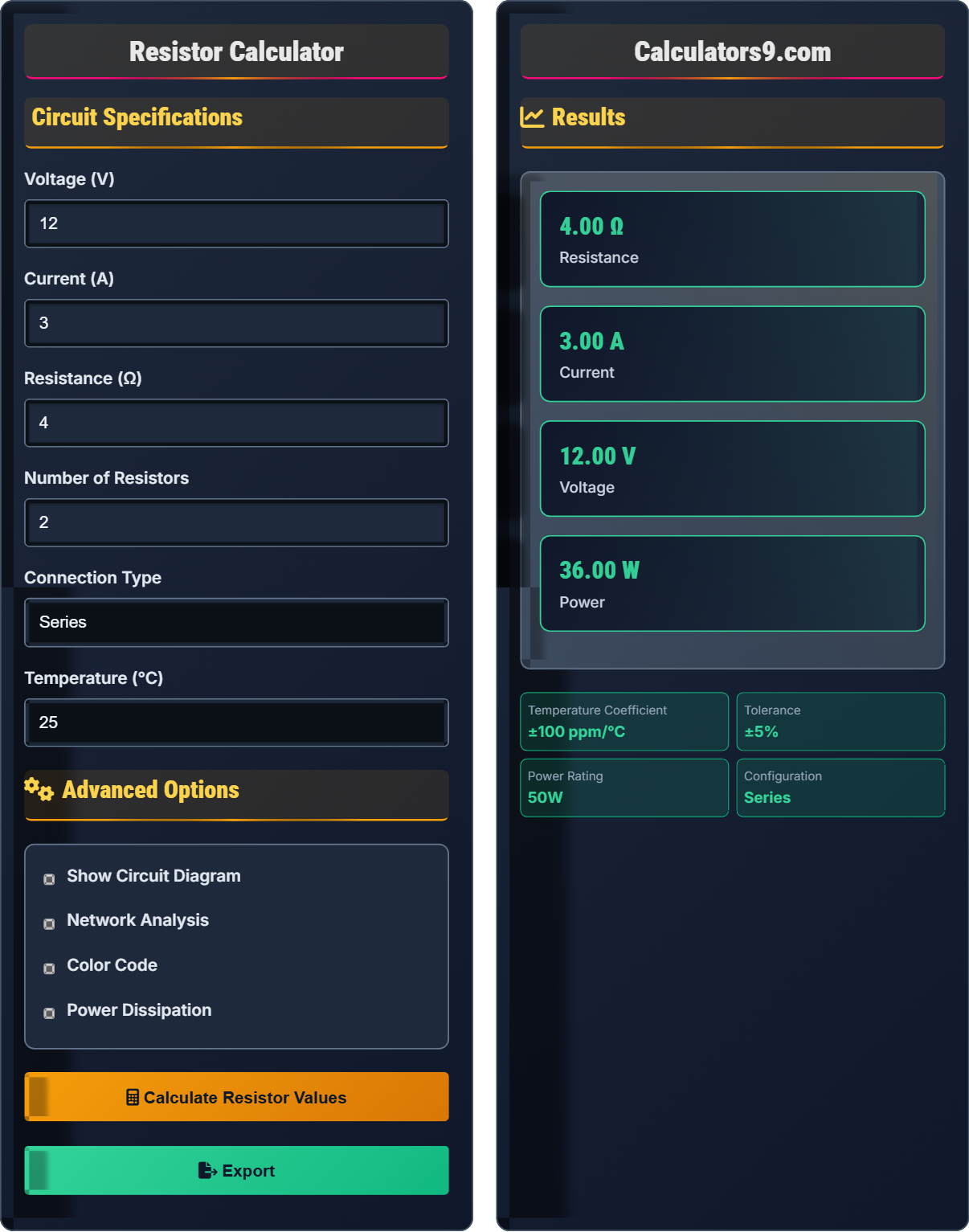
Example: For a 12V circuit with 4Ω resistor:
Current: I = V/R = 12/4 = 3A
Power: P = V×I = 12×3 = 36W
For two 4Ω resistors in series: RT = 4+4 = 8Ω
For two 4Ω resistors in parallel: 1/RT = 1/4+1/4 = 1/2, so RT = 2Ω
Circuit Specifications
Advanced Options
Results
Ohm's Law Fundamentals
Ohm's Law states that the current through a conductor between two points is directly proportional to the voltage across the two points. It's expressed as V = I × R, where V is voltage, I is current, and R is resistance.
Derived formulas from Ohm's Law:
- V = I × R (voltage = current × resistance)
- I = V ÷ R (current = voltage ÷ resistance)
- R = V ÷ I (resistance = voltage ÷ current)
- P = V × I (power = voltage × current)
- Voltage is measured in volts (V)
- Current is measured in amperes (A)
- Resistance is measured in ohms (Ω)
- Power is measured in watts (W)
- Applies to linear resistive elements
Circuit Configurations
In series circuits, resistors are connected end-to-end, while in parallel circuits, resistors are connected across the same two points. Each configuration affects total resistance differently.
Series and parallel calculations:
- Series: RT = R1 + R2 + ... + Rn
- Parallel: 1/RT = 1/R1 + 1/R2 + ... + 1/Rn
- Two resistors in parallel: RT = (R1 × R2) ÷ (R1 + R2)
- Voltage divider: Vout = Vin × (R2 ÷ (R1 + R2))
- Series: Total R increases
- Parallel: Total R decreases
- Series: Current same in all
- Parallel: Voltage same across all
Electrical Engineering Learning Quiz
According to Ohm's Law, if the voltage across a resistor is doubled while the resistance remains constant, what happens to the current?
The correct answer is C) Current doubles. From Ohm's Law: I = V/R. If voltage doubles (V becomes 2V) and resistance stays the same, then I = 2V/R = 2 × (V/R) = 2 × original current.
This demonstrates the direct proportionality between voltage and current in Ohm's Law. When voltage increases by a factor, current increases by the same factor, assuming resistance remains constant.
Ohm's Law: V = I × R, relating voltage, current, and resistance
Direct Proportionality: When one variable increases, the other increases by the same factor
Constant Resistance: Fixed opposition to current flow
• I = V/R (current equals voltage divided by resistance)
• Direct relationship: V ↑ → I ↑
• Assumes linear behavior
• Remember: I = V/R
• If V doubles, I doubles (same R)
• If R doubles, I halves (same V)
• Confusing direct and inverse relationships
• Forgetting to keep resistance constant
• Not understanding proportional relationships
Calculate the total resistance of three resistors connected in series: 10Ω, 20Ω, and 30Ω.
Step 1: Apply the series resistance formula
RT = R1 + R2 + R3
Step 2: Substitute values
RT = 10Ω + 20Ω + 30Ω
Step 3: Calculate
RT = 60Ω
The total resistance is 60 ohms.
In series circuits, total resistance is the sum of individual resistances. This occurs because current must pass through each resistor sequentially, experiencing the full resistance of each element.
Series Circuit: Components connected end-to-end forming single path
Total Resistance: Combined opposition to current flow
Sequential Flow: Current passes through each component
• Series: RT = R1 + R2 + R3 + ...
• Current is same in all resistors
• Voltage divides among resistors
• Always add resistances in series
• Total resistance > any individual resistor
• Same current through all components
• Using parallel formula for series
• Forgetting to add all resistors
• Confusing with parallel connections
Calculate the total resistance of two resistors connected in parallel: 10Ω and 15Ω. Use the formula: 1/RT = 1/R1 + 1/R2.
Step 1: Apply the parallel resistance formula
1/RT = 1/R1 + 1/R2
Step 2: Substitute values
1/RT = 1/10 + 1/15
Step 3: Find common denominator
1/RT = 3/30 + 2/30 = 5/30
Step 4: Solve for RT
RT = 30/5 = 6Ω
The total resistance is 6 ohms.
In parallel circuits, total resistance is always less than the smallest individual resistor. This occurs because current has multiple paths to flow, effectively reducing the overall opposition to current flow.
Parallel Circuit: Components connected across same two points
Multiple Paths: Current can flow through different routesReduced Resistance: Overall opposition decreases
• Parallel: 1/RT = 1/R1 + 1/R2 + ...
• Total resistance < smallest resistor
• Voltage is same across all resistors
• For two resistors: RT = (R1×R2)/(R1+R2)
• Total resistance is always smaller
• Same voltage across all branches
• Adding resistances directly in parallel
• Forgetting to take reciprocal
• Using series formula for parallel
Calculate the power dissipated by a 12Ω resistor with 24V across it. Use the formula: P = V²/R.
Step 1: Apply the power formula
P = V²/R
Step 2: Substitute values
P = (24)²/12
Step 3: Calculate
P = 576/12 = 48W
The resistor dissipates 48 watts of power.
This calculation shows how electrical energy is converted to heat in a resistor. Power dissipation is critical for selecting appropriate resistor ratings to prevent overheating and failure.
Power Dissipation: Energy converted to heat in resistor
Heat Generation: Thermal energy produced by current flow
Power Rating: Maximum safe power for component
• P = V²/R = I²R = VI
• Power is always positive
• Resistors convert electrical to thermal energy
• Use P = V²/R when voltage is known
• Use P = I²R when current is known
• Always check power ratings
• Forgetting to square voltage
• Using wrong formula variant
• Not considering power ratings
In a voltage divider circuit with R1 = 10Ω and R2 = 20Ω, and input voltage of 30V, what is the output voltage across R2?
The correct answer is C) 20V. Using the voltage divider formula: Vout = Vin × (R2/(R1+R2)). Substituting values: Vout = 30 × (20/(10+20)) = 30 × (20/30) = 30 × (2/3) = 20V.
A voltage divider splits input voltage proportionally based on resistor values. The output voltage is the fraction of input voltage equal to the ratio of the lower resistor to the total resistance.
Voltage Divider: Circuit that divides input voltage
Proportional Split: Voltage distributed based on resistance
Series Resistors: Resistors connected end-to-end
• Vout = Vin × (R2/(R1+R2))
• Output is always less than input
• Proportional to resistor ratio
• Output is always less than input
• Higher R2 = higher output
• Use for signal level adjustment
• Using wrong resistor in numerator
• Forgetting to add resistors in denominator
• Not understanding the proportional relationship
FAQ
Q: What's the difference between series and parallel resistor connections?
A: The main differences are:
- Series: Resistors connected end-to-end
- Parallel: Resistors connected across same points
Mathematically:
Series: RT = R1 + R2 + ... (resistance increases)
Parallel: 1/RT = 1/R1 + 1/R2 + ... (resistance decreases)
In series, current is the same through all resistors, but voltage divides. In parallel, voltage is the same across all resistors, but current divides.
Q: How do I read resistor color codes?
A: The 4-band color code system:
- Band 1: First digit
- Band 2: Second digit
- Band 3: Multiplier (number of zeros)
- Band 4: Tolerance (accuracy)
For example, Brown-Black-Red-Gold:
Brown = 1, Black = 0, Red = ×100, Gold = ±5%
Result: 10 × 100 = 1,000Ω ±5%
Common colors: Black(0), Brown(1), Red(2), Orange(3), Yellow(4), Green(5), Blue(6), Violet(7), Gray(8), White(9)