Voltage Drop Calculator
Electrical circuit analysis • 2026 standards
Voltage Drop Formulas:
Show the calculator\( \text{Voltage Drop} = \frac{2 \times K \times L \times I}{CM} \)
\( \text{Percentage Drop} = \frac{\text{Voltage Drop}}{\text{Source Voltage}} \times 100 \)
\( \text{Wire Resistance} = \frac{\rho \times L}{A} \)
\( \text{Power Loss} = I^2 \times R \)
\( \text{Acceptable Drop} = \text{Source Voltage} \times 0.03 \text{ (3%)} \)
These formulas calculate voltage drop in electrical circuits. K is the resistivity constant (12.9 for copper, 21.2 for aluminum), L is the length in feet, I is the current in amperes, and CM is the circular mils of the conductor.
Example: For a 120V circuit with 15A load, 100 ft wire run, 12 AWG copper wire:
CM = 6,530 (12 AWG)
Voltage Drop = (2 × 12.9 × 100 × 15) ÷ 6,530 = 5.94V
Percentage Drop = (5.94 ÷ 120) × 100 = 4.95%
Since 4.95% > 3% recommended limit, a larger wire gauge is needed.
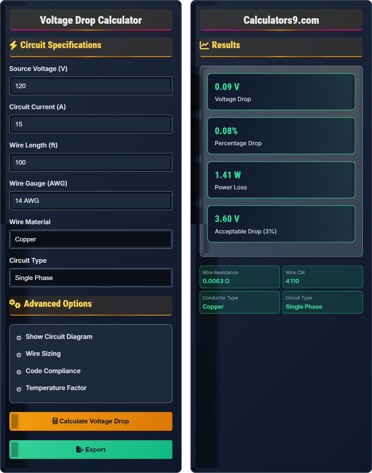
Circuit Specifications
Advanced Options
Results
Voltage Drop Fundamentals
Voltage drop is the reduction in voltage along a conductor due to resistance. It occurs when current flows through a wire and is influenced by wire length, gauge, material, and current. Excessive voltage drop can cause equipment malfunction and energy loss.
Standard voltage drop formulas:
- Single phase: VD = (2 × K × L × I) ÷ CM
- Three phase: VD = (√3 × K × L × I) ÷ CM
- Power loss: P = I² × R
- Keep drop under 3% for feeders
- Keep drop under 5% for branch circuits
- Use proper wire gauge
- Consider circuit length
- Account for temperature
Wire Sizing
American Wire Gauge (AWG) specifies wire diameter and current carrying capacity. Larger numbers represent smaller wires. Proper wire sizing prevents overheating and ensures safety.
Key factors in wire selection:
- Circuit current
- Voltage drop
- Temperature rating
- Conduit fill
- 14 AWG: 15A circuits
- 12 AWG: 20A circuits
- 10 AWG: 30A circuits
- 8 AWG: 40-50A circuits
- 6 AWG: 55-65A circuits
Electrical Engineering Learning Quiz
What is the voltage drop formula for a single-phase circuit?
The correct answer is A) VD = (2 × K × L × I) ÷ CM. This is the standard formula for single-phase voltage drop calculations, where K is the resistivity constant, L is length, I is current, and CM is circular mils.
The factor of 2 in the single-phase formula accounts for the round-trip path of current through both the hot and neutral conductors. The voltage drop occurs in both directions, so the total drop is doubled.
Voltage Drop: Reduction in voltage due to conductor resistance
Circular Mils (CM): Unit of cross-sectional area for wires
Resistivity Constant (K): Material-specific resistance factor
• Single phase: Factor of 2
• Three phase: Factor of √3
• K = 12.9 for copper
• Remember: 2 for single, √3 for three phase
• Copper: K = 12.9, Aluminum: K = 21.2
• Always check NEC requirements
• Forgetting the factor of 2 for single phase
• Using wrong K value for material
• Confusing single and three phase formulas
Calculate the voltage drop for a 120V, 20A single-phase circuit with 100 feet of 12 AWG copper wire. (K = 12.9, CM = 6,530)
Step 1: Apply the single-phase voltage drop formula
VD = (2 × K × L × I) ÷ CM
Step 2: Substitute values
VD = (2 × 12.9 × 100 × 20) ÷ 6,530
Step 3: Calculate
VD = 51,600 ÷ 6,530 = 7.90V
Step 4: Calculate percentage drop
Percentage = (7.90 ÷ 120) × 100 = 6.58%
The voltage drop is 7.90V or 6.58%.
This calculation demonstrates how to apply the voltage drop formula with actual values. The result shows that this setup exceeds the recommended 3% limit, indicating that a larger wire gauge would be needed for proper operation.
Single-Phase Circuit: Circuit with one alternating current path
Wire Gauge: Measurement of wire diameter
Current Carrying Capacity: Maximum safe current for a wire
• Keep drop under 3% for feeders
• Keep drop under 5% for branch circuits
• 12 AWG = 20A maximum
• 12 AWG good for 20A circuits
• For 6.58% drop, use 10 AWG
• Always verify with NEC tables
• Using wrong AWG for current
• Forgetting to check percentage
• Not accounting for length
A 240V, 30A circuit needs to supply power 150 feet away. What is the minimum wire gauge needed to keep voltage drop under 3%? (Use copper wire, K = 12.9)
Step 1: Calculate maximum allowable voltage drop
Max VD = 240V × 0.03 = 7.2V
Step 2: Rearrange voltage drop formula to solve for CM
CM = (2 × K × L × I) ÷ VD
Step 3: Substitute values
CM = (2 × 12.9 × 150 × 30) ÷ 7.2
Step 4: Calculate
CM = 116,100 ÷ 7.2 = 16,125 CM
Step 5: Find wire gauge
Looking at AWG tables, 8 AWG has 16,510 CM, which is sufficient.
8 AWG wire is needed for this circuit.
This problem demonstrates how to work backwards from a voltage drop requirement to determine the necessary wire size. The rearrangement of the voltage drop formula allows us to solve for the required cross-sectional area.
Wire Sizing: Selecting appropriate wire gauge for circuit requirements
Cross-Sectional Area: Area of wire perpendicular to current flow
Circuit Requirements: Voltage, current, and distance needs
• Rearrange formula to solve for unknown
• Use next larger gauge if between sizes
• Always check current capacity too
• Round up to next standard gauge
• Check current capacity also
• Consider temperature derating
• Not solving for CM first
• Using wrong formula arrangement
• Forgetting current capacity check
Calculate the power loss in watts for a circuit with 15A current and 0.05 ohms resistance.
Step 1: Apply the power loss formula
Power Loss = I² × R
Step 2: Substitute values
Power Loss = (15)² × 0.05
Step 3: Calculate
Power Loss = 225 × 0.05 = 11.25W
The power loss in the circuit is 11.25 watts.
Power loss represents energy converted to heat in the conductor due to resistance. This is why undersized wires can overheat and potentially cause fires. The quadratic relationship with current means that doubling the current quadruples the power loss.
Power Loss: Energy lost as heat in electrical conductors
I²R Losses: Resistive losses proportional to current squared
Heat Generation: Thermal energy produced by electrical resistance
• Power Loss = I² × R
• Loss increases with current squared
• Larger wires have less resistance
• Minimize resistance to reduce losses
• Proper wire sizing prevents overheating
• Consider ambient temperature effects
• Forgetting the squared relationship
• Not considering thermal effects
• Ignoring cumulative losses
How does temperature affect wire resistance?
The correct answer is B) Resistance increases with temperature. As temperature increases, atomic vibrations in the conductor increase, causing more collisions with electrons and thus higher resistance.
This temperature coefficient effect is important in electrical design because warm wires have higher resistance, leading to greater voltage drops and power losses. This is why wire ampacity ratings are based on specific temperature conditions.
Temperature Coefficient: How resistance changes with temperature
Ampacity: Maximum safe current for a conductor
Thermal Effects: Temperature-related changes in electrical properties
• Copper: 0.00393/°C temperature coefficient
• Resistance increases with temperature
• Derate for high temperatures
• Use derating factors for high temperatures
• Consider ambient conditions
• Account for heat buildup in conduits
• Ignoring temperature effects
• Not derating for high temps
• Forgetting conduit fill effects
FAQ
Q: How do I calculate voltage drop for a three-phase circuit?
A: For three-phase circuits, use this formula:
$$ \text{VD} = \frac{\sqrt{3} \times K \times L \times I}{CM} $$
Where √3 ≈ 1.732. The factor √3 accounts for the phase relationship in three-phase systems.
For example, with 208V, 30A, 100 ft, 10 AWG copper:
CM = 10,380 (10 AWG)
VD = (1.732 × 12.9 × 100 × 30) ÷ 10,380 = 6.48V
Percentage = (6.48 ÷ 208) × 100 = 3.11%
Q: What's the difference between copper and aluminum wire?
A: The main differences relate to resistivity and cost:
- Copper: K = 12.9, better conductivity, more expensive
- Aluminum: K = 21.2, higher resistance, less expensive
Mathematically, for the same voltage drop:
Aluminum requires larger gauge than copper
For example, if 12 AWG copper is needed, 10 AWG aluminum would be required for similar performance.
Aluminum is commonly used for service entrances and large feeders due to cost savings.