Inductance Combiner
Physics & Engineering Tool • Electromagnetic Calculations
Series Inductance Formula:
Show the calculator\( L_{total} = L_1 + L_2 + L_3 + ... + L_n \)
\( V_L = L \frac{di}{dt} \)
\( E = \frac{1}{2}LI^2 \)
Where:
- \( L_{total} \) = total inductance (H)
- \( L_i \) = individual inductance (H)
- \( V_L \) = induced voltage (V)
- \( I \) = current (A)
- \( E \) = energy stored (J)
In a series inductor configuration, the total inductance is the sum of all individual inductances. This is because the same current flows through all inductors, and the magnetic fields add together. The voltage across the combination is the sum of voltages across each inductor.
Example: Three inductors in series: L₁=2mH, L₂=3mH, L₃=5mH
\( L_{total} = 2 + 3 + 5 = 10 \) mH
If I = 1A, then E = ½ × 10 × 10⁻³ × 1² = 5 mJ
Thus, the total inductance is 10mH and energy stored is 5 millijoules.
Inductor Values
Advanced Options
Results
| Parameter | Value | Unit |
|---|---|---|
| Total Inductance | 10.0 | mH |
| Energy Stored | 5.0 | mJ |
| Inductive Reactance | 3.77 | Ω |
| Current | 1.0 | A |
| Frequency | 60.0 | Hz |
Based on the calculated inductance of 10.0 mH at 1A current:
- Energy Stored: 5.0 mJ
- Energy Density: 5.0 mJ/mH
- Power Rating: Based on current and duty cycle
- Time Constant: τ = L/R (depends on circuit resistance)
Energy is stored in the magnetic field around the inductor and can be released when current decreases.
| Configuration | Inductors | Total L (mH) | Energy (mJ) | X_L (Ω) |
|---|---|---|---|---|
| Config 1 | 3 | 10.0 | 5.0 | 3.77 |
| Config 2 | 2 | 10.0 | 5.0 | 3.77 |
Series Inductance Fundamentals
Inductance is the property of an electrical conductor that opposes changes in current flow. When current changes, it creates a changing magnetic field which induces a voltage in the conductor. This self-induced voltage opposes the change in current, following Lenz's Law. The unit of inductance is the Henry (H).
When inductors are connected in series, the total inductance is simply the sum of all individual inductances:
This occurs because the same current flows through all inductors in series, and the magnetic fields add together. The total voltage across the series combination is the sum of voltages across each inductor.
Series inductor circuits are essential in numerous fields:
- Power Electronics: Choke filters, DC-DC converters
- RF Engineering: Antenna matching, filter design
- Motor Control: Current limiting, smoothing
- Transformer Design: Leakage inductance modeling
- Chokes in power supplies to smooth current
- Transformer windings connected in series
- Motor windings in series configuration
- RF choke coils in signal circuits
Inductance Concepts
Inductance: Opposition to change in current; stores energy in magnetic field.
\(L_{total} = L_1 + L_2 + L_3 + ... + L_n\)
Where L_total = sum of all series inductances.
- Total L > any individual L
- Current same through all inductors
- Same magnetic flux linkage
Applications
Energy stored: E = ½LI²
- Identify series inductors
- Sum individual inductances
- Calculate reactance if AC
- Determine energy storage
- DC: Inductors act as short circuits
- AC: Inductive reactance increases with frequency
- Mutual inductance affects total L
- Core saturation limits inductance
Series Inductance Learning Quiz
What happens to the total inductance when two identical inductors are connected in series?
The answer is B) It doubles. In series, inductances add arithmetically: L_total = L₁ + L₂. If L₁ = L₂ = L, then L_total = L + L = 2L. This is because the same current flows through both inductors, and their magnetic fields add together, effectively creating a single inductor with twice the inductance.
This question tests the fundamental understanding of series inductance. Unlike capacitors where series connection decreases total capacitance, inductors behave similarly to resistors in series - the total inductance increases. This is because the magnetic flux linkages add up when inductors are in series, creating a stronger combined magnetic field.
Inductance: Opposition to current change (Henry)
Series: Connected end-to-end
Flux Linkage: Magnetic field interaction
• L_total = sum of individual inductances
• Current same through all series inductors
• Magnetic fields add in series
• Remember: Inductors add in series (like resistors)
• Unlike capacitors which subtract in series
• Confusing with capacitor series formula
• Forgetting that inductors behave like resistors in series
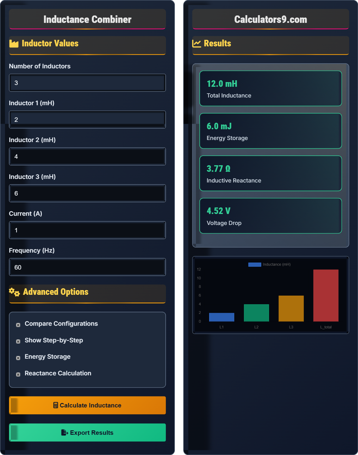
Three inductors (L₁=2mH, L₂=3mH, L₃=5mH) are connected in series to a 12V AC source at 60Hz. Calculate the total inductance, inductive reactance, current, and energy stored when current reaches 1A.
Step 1: Calculate total inductance
L_total = L₁ + L₂ + L₃ = 2 + 3 + 5 = 10 mH
Step 2: Calculate inductive reactance
X_L = 2πfL = 2π × 60 × 10 × 10⁻³ = 3.77 Ω
Step 3: Calculate current (using Ohm's Law for AC)
I = V/X_L = 12/3.77 = 3.18 A
Step 4: Calculate energy stored at 1A current
E = ½LI² = ½ × 10 × 10⁻³ × 1² = 5 mJ
The total inductance is 10mH, inductive reactance is 3.77Ω, current is 3.18A, and energy stored at 1A is 5mJ.
This problem demonstrates the relationship between inductance, frequency, and reactance in AC circuits. The inductive reactance (X_L = 2πfL) shows how inductors oppose AC current more strongly at higher frequencies. The energy stored (E = ½LI²) depends on the inductance and the square of the current, similar to how capacitors store energy.
Inductive Reactance: Opposition to AC current (Ω)
AC Circuit: Alternating current systemEnergy Storage: Magnetic field energy (Joules)
• X_L = 2πfL (frequency-dependent)
• E = ½LI² (energy storage formula)
• Higher frequency = higher reactance
• Reactance increases linearly with frequency
• Energy stored depends on current squared
• In series: L_total = sum of L's
• Using DC resistance instead of AC reactance
• Forgetting to convert mH to H in calculations
• Confusing reactance with resistance
FAQ
Q: What is the difference between inductance and inductive reactance, and how do they relate to each other?
A: Inductance (L) is a property of the physical component itself - it measures how much voltage is induced when current changes. It's measured in Henrys (H) and depends on the physical characteristics of the inductor (number of turns, core material, etc.).
Inductive reactance (X_L) is the opposition that an inductor presents to alternating current. It's measured in Ohms (Ω) and depends on both the inductance and the frequency of the AC signal: X_L = 2πfL.
While inductance is constant for a given component, inductive reactance increases with frequency. At DC (0 Hz), inductive reactance is zero, so the inductor behaves like a short circuit. At high frequencies, the reactance becomes very large, effectively blocking current flow.
Q: How do series inductor calculations apply to real-world engineering problems?
Can you provide examples of how these concepts are used in practice?
A: Series inductors are fundamental in electrical engineering applications:
- Power Supplies: Choke inductors in SMPS to smooth current ripple
- Filters: LC filters where inductors are used in series with load
- Motor Control: Series inductors limit inrush current and smooth motor operation
- RF Circuits: Impedance matching networks and filter design
For example, in a DC-DC converter, engineers use series inductors to store energy during the on-time and release it during the off-time. The total inductance affects the ripple current and energy storage capability. When designing a boost converter with multiple inductors in series, the total inductance increases, reducing ripple current but increasing the physical size and cost.