Parallel Resistor Calculator
Physics & Engineering Tool • Electrical Calculations
Parallel Resistor Formula:
Show the calculator\( \frac{1}{R_{eq}} = \frac{1}{R_1} + \frac{1}{R_2} + \frac{1}{R_3} + ... + \frac{1}{R_n} \)
\( I_i = \frac{V}{R_i} \)
\( I_{total} = I_1 + I_2 + I_3 + ... + I_n \)
\( V = V_1 = V_2 = V_3 = ... = V_n \)
Where:
- \( R_{eq} \) = equivalent resistance (Ω)
- \( R_i \) = individual resistor value (Ω)
- \( I_i \) = current through resistor i (A)
- \( I_{total} \) = total current (A)
- \( V \) = voltage across all resistors (V)
In a parallel circuit, resistors are connected side-by-side, and the voltage is the same across all resistors. The equivalent resistance is always less than the smallest individual resistance. Current divides among the resistors inversely proportional to their resistances.
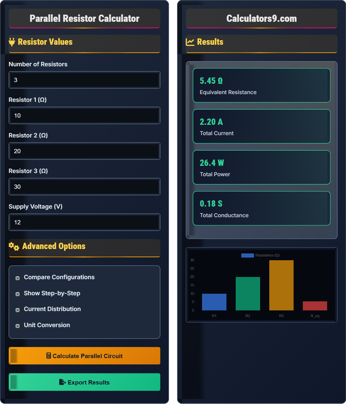
Example: Three resistors in parallel: R₁=10Ω, R₂=20Ω, R₃=30Ω
\( \frac{1}{R_{eq}} = \frac{1}{10} + \frac{1}{20} + \frac{1}{30} = \frac{6+3+2}{60} = \frac{11}{60} \)
\( R_{eq} = \frac{60}{11} = 5.45 \) Ω
If V = 12V, then I_total = 12/5.45 = 2.20A
I₁ = 12/10 = 1.2A, I₂ = 12/20 = 0.6A, I₃ = 12/30 = 0.4A
Thus, equivalent resistance is 5.45Ω and total current is 2.20A.
Resistor Values
Advanced Options
Results
| Parameter | Value | Unit |
|---|---|---|
| Equivalent Resistance | 5.45 | Ω |
| Total Current | 2.20 | A |
| Total Power | 26.4 | W |
| Supply Voltage | 12.0 | V |
| Number of Resistors | 3 | - |
| Resistor | Resistance (Ω) | Voltage (V) | Current (A) | Power (W) |
|---|---|---|---|---|
| R₁ | 10.0 | 12.0 | 1.20 | 14.4 |
| R₂ | 20.0 | 12.0 | 0.60 | 7.2 |
| R₃ | 30.0 | 12.0 | 0.40 | 4.8 |
| Configuration | Resistors | Equivalent R (Ω) | Total I (A) | Power (W) |
|---|---|---|---|---|
| Config 1 | 3 | 5.45 | 2.20 | 26.4 |
| Config 2 | 2 | 9.38 | 1.28 | 15.4 |
Parallel Resistor Fundamentals
In a parallel circuit, resistors are connected side-by-side with their ends connected to common points. The voltage across each resistor is the same as the supply voltage, but the current divides among the resistors. The equivalent resistance is always less than the smallest individual resistance.
The fundamental formulas for parallel circuits are:
\(V_{total} = V_1 = V_2 = V_3 = ... = V_n\)
\(I_{total} = I_1 + I_2 + I_3 + ... + I_n\)
Where:
- \(R_{eq}\) = equivalent resistance (Ω)
- \(V_{total}\) = total voltage (V)
- \(I_{total}\) = total current (A)
- \(R_i, I_i, V_i\) = individual resistor values
Parallel resistor circuits are essential in numerous fields:
- Electronics: Current mirrors, current dividers, bias circuits
- Power Systems: Load distribution, redundancy systems
- Instrumentation: Shunt resistors, current sensing
- Household Wiring: Lights and appliances in parallel
- Household outlets connected in parallel
- LED arrays with parallel current paths
- Shunt resistors in ammeter circuits
- Power supply current sharing
Parallel Circuit Concepts
Parallel circuit: Resistors connected with same voltage across all, current divides.
\(\frac{1}{R_{eq}} = \frac{1}{R_1} + \frac{1}{R_2} + \frac{1}{R_3} + ... + \frac{1}{R_n}\)
Where R_eq = equivalent resistance of parallel combination.
- Equivalent R < any individual R
- Voltage same across all resistors
- Current divides inversely to resistance
Applications
Current through each resistor: Iᵢ = V / Rᵢ
- Calculate equivalent resistance
- Determine total current
- Calculate individual currents
- Verify total current equals sum of branch currents
- Smaller resistance gets more current
- Adding resistors decreases total resistance
- One failure doesn't break circuit
- Total current increases with more branches
Parallel Resistor Learning Quiz
In a parallel circuit with multiple resistors, how does the equivalent resistance compare to the individual resistors?
The answer is C) Equivalent resistance is less than smallest resistor. In a parallel circuit, the equivalent resistance is always smaller than the smallest individual resistance. This is because adding parallel paths provides more ways for current to flow, effectively reducing the overall resistance.
This question tests the fundamental understanding of parallel circuits. The reciprocal relationship (1/R_eq = 1/R₁ + 1/R₂ + ...) ensures that adding more parallel resistors always decreases the equivalent resistance. This is counterintuitive compared to series circuits where adding resistors increases total resistance.
Parallel Circuit: Components connected with same voltage across all
Equivalent Resistance: Single resistor that replaces circuit
Reciprocal: Inverse relationship (1/x)
• R_eq < R_smallest (in parallel)
• More parallel paths = lower resistance
• Voltage same across all parallel components
• Remember: Parallel = Less resistance
• Think of water pipes: more pipes = easier flow
• Adding resistances in parallel (that's series)
• Forgetting that equivalent resistance is smaller
Two resistors (R₁=6Ω, R₂=12Ω) are connected in parallel to a 12V power supply. Calculate the equivalent resistance, total current, and current through each resistor.
Step 1: Calculate equivalent resistance
1/R_eq = 1/R₁ + 1/R₂ = 1/6 + 1/12 = 2/12 + 1/12 = 3/12 = 1/4
R_eq = 4Ω
Step 2: Calculate total current using Ohm's Law
I_total = V / R_eq = 12V / 4Ω = 3A
Step 3: Calculate current through each resistor
I₁ = V / R₁ = 12V / 6Ω = 2A
I₂ = V / R₂ = 12V / 12Ω = 1A
Step 4: Verify current division
I_total = I₁ + I₂ = 2A + 1A = 3A ✓
Verification: The smaller resistor (6Ω) gets more current (2A) than the larger resistor (12Ω) which gets 1A, demonstrating that current divides inversely proportional to resistance.
The equivalent resistance is 4Ω, total current is 3A, with 2A through R₁ and 1A through R₂.
This problem demonstrates the inverse relationship between resistance and current in parallel circuits. The 6Ω resistor has half the resistance of the 12Ω resistor, so it carries twice the current (2A vs 1A). This confirms that current divides inversely proportional to resistance in parallel circuits. The equivalent resistance (4Ω) is indeed less than the smallest individual resistor (6Ω).
Current Division: Current splits among parallel paths
Inverse Proportion: Current ∝ 1/Resistance
Parallel Paths: Multiple current routes available
• 1/R_eq = sum of 1/R_individual
• Current ∝ 1/Resistance (in parallel)
• I_total = sum of branch currents
• Smaller resistor gets more current
• Always verify: I_total = sum of branch currents
• Equivalent resistance is always smallest in parallel
• Adding resistances instead of using reciprocal formula
• Forgetting that voltage is same across all parallel resistors
• Not verifying that branch currents sum to total current
FAQ
Q: What happens if one resistor in a parallel circuit fails short?
A: If one resistor in a parallel circuit fails short (becomes zero resistance), it creates a direct path from positive to negative terminals of the power supply, bypassing the other resistors. This causes a dramatic increase in total current, potentially blowing fuses or tripping circuit breakers. The voltage across the other resistors drops to nearly zero because the shorted path offers minimal resistance.
However, if a resistor fails open (becomes infinite resistance), the other resistors continue to operate normally. The total resistance increases (since one parallel path is removed), and the total current decreases. This is a major advantage of parallel circuits compared to series circuits.
For example, in household wiring, if one light bulb burns out (open circuit), the other lights remain on because they're connected in parallel. But if a short circuit occurs in one appliance, it can cause a fuse to blow, protecting the entire circuit.
Q: How do parallel resistor calculations apply to real-world engineering problems?
Can you provide examples of how these concepts are used in practice?
A: Parallel resistor circuits are fundamental in electrical engineering applications:
- Power Distribution: Multiple loads connected in parallel to share power
- Current Sharing: Multiple power supplies in parallel for redundancy
- Amplifier Design: Feedback networks and bias circuits
- Measurement Systems: Shunt resistors for current sensing
For example, when designing a power supply for multiple loads, engineers use parallel connections to ensure each load receives the same voltage. If a system requires 12V at 10A but only has 5A-rated power supplies available, they can connect two supplies in parallel. Each supply would then deliver about 5A, providing the total required current while maintaining the voltage.
Another common application is in shunt resistor circuits for current measurement. A small-value precision resistor is placed in parallel with a galvanometer to create an ammeter. The parallel connection allows most current to flow through the low-resistance shunt while a small, measurable portion flows through the meter.