Torque Calculator
Rotational dynamics analysis • 2026 physics
Torque Formula:
Show the calculator\( \tau = rF\sin(\theta) \)
Where:
- \( \tau \) = torque (Newton-meters)
- \( r \) = lever arm length (meters)
- \( F \) = applied force (Newtons)
- \( \theta \) = angle between force and lever arm (degrees)
This fundamental equation describes rotational force, which causes angular acceleration in objects. Torque is the rotational equivalent of linear force. The lever arm is the perpendicular distance from the axis of rotation to the line of action of the force. Maximum torque occurs when the force is applied perpendicular to the lever arm (θ = 90°).
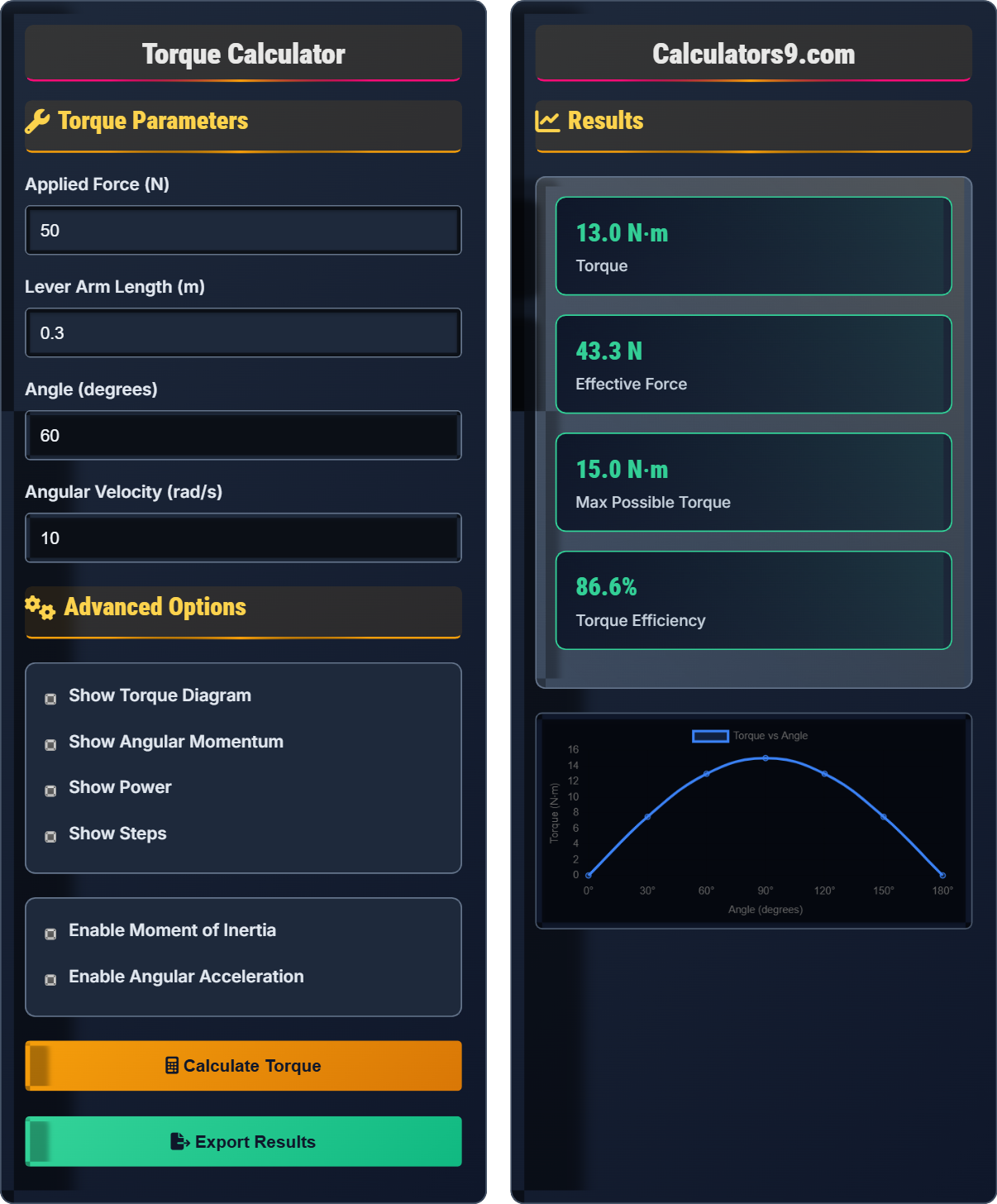
Example: A force of 50 N applied at a 30 cm (0.3 m) lever arm at an angle of 60°:
\( \tau = 0.3 \times 50 \times \sin(60°) = 0.3 \times 50 \times 0.866 = 12.99 \) N⋅m
Thus, the torque is approximately 13.0 N⋅m.
Torque Parameters
Advanced Options
Results
| Parameter | Value | Description |
|---|
| Power Type | Value | Significance |
|---|
| Momentum Property | Value | Units |
|---|
Comprehensive Torque Guide
Torque, also known as moment of force, is the rotational equivalent of linear force. It measures the tendency of a force to cause rotation around an axis. Torque is a vector quantity with both magnitude and direction, causing angular acceleration in objects. The concept is fundamental to understanding rotational mechanics, from simple tools to complex machinery.
The fundamental equation is:
Where:
- \(\tau\) = torque (Newton-meters)
- \(r\) = lever arm length (meters)
- \(F\) = applied force (Newtons)
- \(\theta\) = angle between force and lever arm (degrees)
Torque connects to other rotational quantities:
Where I is moment of inertia, α is angular acceleration, L is angular momentum, and ω is angular velocity.
- Maximum Torque: Occurs when force is perpendicular to lever arm (θ = 90°)
- Mechanical Advantage: Longer levers provide greater torque with less force
- Vector Nature: Torque has direction (clockwise vs counterclockwise)
- Static Equilibrium: Net torque must be zero for rotational equilibrium
Torque Fundamentals
Rotational force causing angular acceleration around an axis.
\(\tau = rF\sin(\theta)\)
Where τ=torque, r=lever arm, F=force, θ=angle.
- Max torque at 90° angle
- Longer arms = more torque
- Force ⊥ lever arm = max efficiency
Applications
Gears, engines, and rotating machinery rely on torque principles.
- Automotive engines
- Industrial motors
- Power tools
- Robotics
- Angle affects efficiency
- Arm length affects leverage
- Friction reduces effective torque
- Material strength limits
Torque Learning Quiz
At what angle between the applied force and lever arm is torque maximized?
The answer is C) 90°. From the torque formula τ = rFsin(θ), torque is maximized when sin(θ) reaches its maximum value of 1, which occurs when θ = 90°. At this angle, the force is perpendicular to the lever arm, providing maximum rotational effect. At 0° and 180°, sin(θ) = 0, resulting in zero torque regardless of force magnitude.
Think of pushing a door. When you push perpendicular to the door (toward the hinges), you get maximum effectiveness. When you push parallel to the door (along its surface), you get no rotational effect. This demonstrates the importance of the angle in torque calculations.
Torque: Rotational force causing angular acceleration
Lever Arm: Perpendicular distance from axis to force line
Angle: Between force vector and lever arm
• Max torque at 90° angle
• Zero torque at 0° or 180°
• Torque ∝ sin(θ)
• Push perpendicular for maximum effect
• Think of door handles positioned for optimal angle
• Sine function peaks at 90°
• Thinking force magnitude alone determines torque
• Forgetting the angle dependency
• Confusing lever arm with total length
A mechanic applies 80 N of force at the end of a 0.4 m wrench at an angle of 75° to the wrench handle. Calculate the resulting torque.
Using the torque formula: τ = rFsin(θ)
Given:
- r = 0.4 m (lever arm)
- F = 80 N (applied force)
- θ = 75° (angle between force and lever)
Step 1: Calculate sin(75°) = 0.966
Step 2: Substitute values: τ = 0.4 × 80 × 0.966
Step 3: Calculate: τ = 31.04 N⋅m
Therefore, the torque is approximately 31.0 N⋅m.
This calculation shows how the angle affects the effective force component. Even though the full 80 N is applied, only about 77.3 N (80 × sin(75°)) contributes to rotational motion. This is why mechanics position themselves to apply force at optimal angles.
Effective Force: Component of force perpendicular to lever
Perpendicular Component: F⊥ = Fsin(θ)
Rotational Effect: Depends on perpendicular force
• Only perpendicular force component creates torque
• Use sine of angle between vectors
• Torque increases with lever arm length
• Remember: τ = rFsin(θ)
• Calculate perpendicular force component
• Check angle is between force and lever
• Using cosine instead of sine
• Forgetting to convert to radians
• Using angle from horizontal instead of lever
A worker needs to generate 100 N⋅m of torque to tighten a bolt. If they have a wrench with a 0.3 m lever arm, what minimum force must they apply at 90° to achieve this torque? How does this change if they can only apply force at 60°?
Part 1: At 90° angle
Using τ = rFsin(θ), rearrange to solve for F: F = τ/(r×sin(θ))
At 90°: F = 100/(0.3 × sin(90°)) = 100/(0.3 × 1) = 333.3 N
Part 2: At 60° angle
At 60°: F = 100/(0.3 × sin(60°)) = 100/(0.3 × 0.866) = 100/0.260 = 384.6 N
Therefore, 333.3 N is needed at 90°, but 384.6 N is needed at 60°. The worker needs about 15% more force at 60°.
This demonstrates mechanical advantage. When force is applied perpendicularly, the worker gets maximum effectiveness from their effort. At 60°, some of the force is wasted in a direction that doesn't contribute to rotation, requiring more total force to achieve the same torque.
Mechanical Advantage: Ratio of output to input force
Force Multiplication: Achieved through lever arms
Efficiency: How effectively force creates rotation
• F = τ/(r×sin(θ)) to find required force
• Perpendicular application is most efficient
• Oblique angles require more force
• Use longer wrench for same torque with less force
• Position for perpendicular force application
• Calculate required force for safety
• Forgetting angle affects required force
• Not accounting for mechanical advantage
• Confusing torque with force
A flywheel with moment of inertia 2.5 kg⋅m² experiences a net torque of 50 N⋅m. Calculate the angular acceleration. If the flywheel starts from rest, what will be its angular velocity after 4 seconds?
Step 1: Calculate angular acceleration using τ = Iα
Rearranging: α = τ/I = 50/2.5 = 20 rad/s²
Step 2: Calculate final angular velocity using kinematic equation
ω = ω₀ + αt, where ω₀ = 0 (starts from rest)
ω = 0 + 20 × 4 = 80 rad/s
Step 3: Convert to rpm if needed: 80 rad/s × (60 s/min) × (1 rev/2π rad) = 764 rpm
Therefore, the angular acceleration is 20 rad/s², and the final angular velocity is 80 rad/s (764 rpm).
This connects rotational and linear dynamics. Just as F = ma relates force to linear acceleration, τ = Iα relates torque to angular acceleration. The moment of inertia plays the role of mass in rotational motion, representing resistance to angular acceleration.
Moment of Inertia: Resistance to angular acceleration
Angular Acceleration: Rate of change of angular velocity
Rotational Kinematics: Similar to linear kinematics
• τ = Iα (rotational equivalent of F = ma)
• Kinematic equations apply to rotation
• I depends on mass distribution
• Remember: bigger I = harder to accelerate
• Mass farther from axis increases I significantly
• Analogous to linear motion equations
• Forgetting moment of inertia in torque calculations
• Confusing angular with linear acceleration
• Using wrong kinematic equations
Which statement about angular momentum is CORRECT?
The answer is C) L = Iω for all rigid bodies. Angular momentum is the rotational equivalent of linear momentum, defined as L = Iω for rigid bodies, where I is the moment of inertia and ω is the angular velocity. Angular momentum is conserved only in the absence of external torques (net torque = 0), similar to how linear momentum is conserved only in the absence of external forces.
This connects torque to angular momentum through the relationship τ = dL/dt. When no external torque acts on a system, angular momentum remains constant. This principle explains phenomena like figure skaters spinning faster when they pull in their arms (reducing I, increasing ω to conserve L).
Angular Momentum: L = Iω for rigid bodies
Conservation: L constant when Στ = 0
Relationship: τ = dL/dt
• L = Iω for rigid bodies
• Conservation requires Στ_ext = 0
• Torque changes angular momentum
• Think of ice skater pulling arms in
• Iω = constant (conservation)
• Torque is rate of change of angular momentum
• Thinking momentum is always conserved (requires no external torque)
• Confusing L = mvr with L = Iω
• Forgetting moment of inertia in calculations
FAQ
Q: How does the parallel axis theorem relate to moment of inertia in torque calculations?
A: The parallel axis theorem is crucial when calculating moment of inertia about axes not through the center of mass. The theorem states:
\( I = I_{cm} + md^2 \)
Where \( I_{cm} \) is the moment of inertia about the center of mass, m is the total mass, and d is the distance between the parallel axes.
For example, consider a rod of mass M and length L rotating about one end rather than its center. The moment of inertia about the center is \( I_{cm} = \frac{1}{12}ML^2 \). Using the parallel axis theorem with d = L/2:
\( I = \frac{1}{12}ML^2 + M\left(\frac{L}{2}\right)^2 = \frac{1}{12}ML^2 + \frac{1}{4}ML^2 = \frac{1}{3}ML^2 \)
This increased moment of inertia means more torque is required to achieve the same angular acceleration when rotating about the end rather than the center.
Q: What is the relationship between torque, power, and angular velocity in rotating machinery?
A: The relationship between torque, power, and angular velocity is fundamental to rotating machinery:
\( P = \tau\omega \)
Where P is power, τ is torque, and ω is angular velocity.
This equation shows that for a given power output, increasing torque requires decreasing angular velocity (and vice versa). This is why vehicles have transmissions—to allow the engine to operate efficiently by trading torque for speed or vice versa.
In practical terms:
- Low Speed, High Torque: Heavy lifting, starting loads
- High Speed, Low Torque: Maintaining motion, high RPM operations
- Constant Power: Turbines, electric motors in certain applications
This relationship is essential for designing drivetrains, selecting motors, and optimizing mechanical systems.